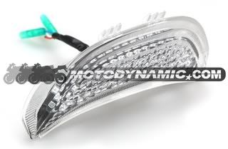
Alright, Big shout out to jacoviii for bringing my attention to the possibilities of this light! Made for an 03-06 CBR 600rr/ 04-07 CBR 100rr, its actually a perfect fit for the max and only cost about $65 shipped. I received it in 4 days and it looked like a well made unit. The included wiring Harness was also very nicely done.
In order to mount this light to the Vmax, there are a few modifications that need to be made to the inner fender. They are fairly simple once you get the idea of what is going on. I did all the metal work with tin snips, pliers, and a drill on the living room floor of my condo. A proper garage setup and some actual tools/metal saw would make this process much more efficient/professional looking!!
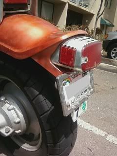
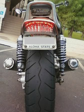
Here is a pic of the what the bike looked like when we started. The stickers bellow the plate are for the Hawaii safety check.
The first step is to remove the rear fender and inner fender from the bike. Keep the mounting bolts with you as we will use them during the mock-up as well.
Once the fender is removed, The rear mounts must be removed. *IMPORTANT* Save the square flanged nuts (or whatever they are called) that fit into these mounts. They will be very useful later on.
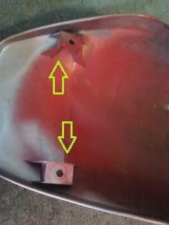
I used a soldering iron to score along each edge and the broke off very easily. A dremel tool and small cut-off disk would also work well. A sharp knife easily scraped off any remaining bumps.
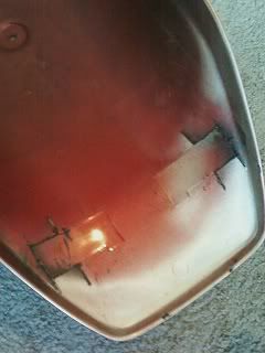
At this point, I put the new light in the empty fender to see how it would mount.
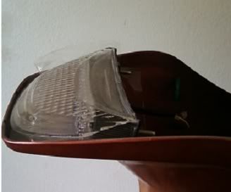
The mount for the stock mount is about an an inch and a half too far back for the new LED so the old mount must be removed and the inner fender shortened.
I started by cutting slits into either side of the inner fender so about 1/4" past the needed clearance for the new light.
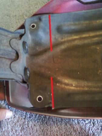
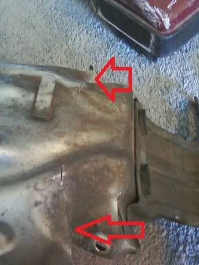
After Cutting the slits, you can also go ahead and cut off the entire section above the rubber grommets for the old light. Bend the entire rear section down 90 Degrees. I did this in reverse order in the pictures and in multiple steps as I kept checking the clearance over the tire.
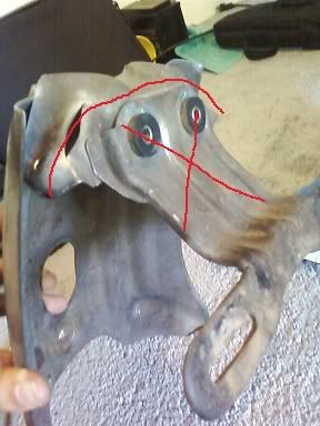
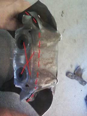
Once the new flange was bent down, I pounded out the dips in it to make it a straight, flat piece. Then I put it back into the rear fender, and mocked up the new led light. I did this to get an idea of where the holes should be drilled in the flange for the LED mounting bolts to go through. After the holes were drilled, I cut off excess metal on the outside of them. the Final product should look something like this:
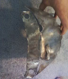
For the bolt holes, I believe I used a 5/16 inch drill bit; it seems big, but it must be large enough to fit the spacer with a rubber grommet on it. I will explain this in a bit.
At this point, I began to consider how I was going to mount the rear liscense plate. I like the looks of it under the light, so a new mount was going to have to be added to the inner fender. To this end, I took the Hawaii safety sticker mounting plate and (you can see this under the license plate in the starting picture of the bike up top), bent it up to curve under the light and drilled mounting holes in it and the inner fender.
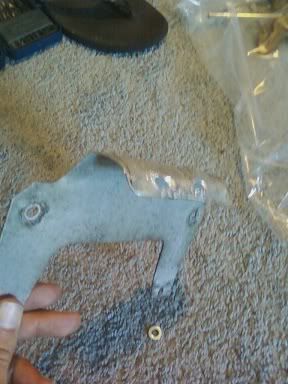
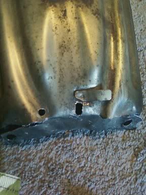
The double sized hole on the inner fender provides some angle adjustment to the mounting of the plate. I also drilled slots in the license mount (safety sticker thing) to allow for some left to right adjustment. This is what it looked like all together:
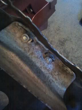
From the bottom:
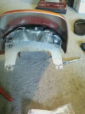
From the back: (Yes yes I know how crappy this all looks, but just keep reading and remember I have no tools or proper work area!)
Now its time to make sure the angle of the mounting flange is correct to position the light in the fender.
Attach the inner fender to the fender using the mounting bolt to line everything up.
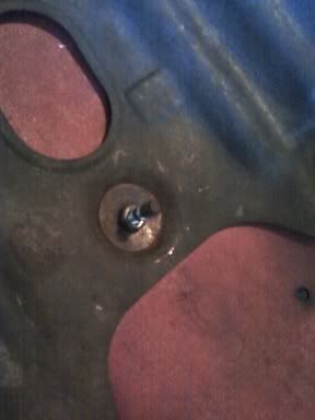
Now how are we going to actually bolt in the light? The bolts coming out of the unit are a little skinny and don't mount to a flat surface as they have a section of plastic around them.
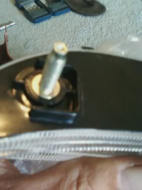
Remember those mounting nuts I told you to save out of the rear light mounts on the fender? It turns out that they fit perfectly (after grinding 1/16 of an inch off of the inner sides ) into the recess of the new light mounts!! Here is one with a rubber grommet on it.
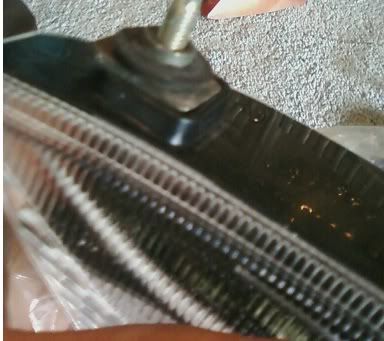
They will provide an even mounting pressure on the light and work perfectly to hold a rubber grommet. This will give the light a small amount of vibration insulation from the inner fender. (Its how the original was installed so I figured it would be good to copy!)
Here is a picture of the mounting hardware I used. I believe the grommet was 5/16 inside diameter. It just stretched a bit to fit over the square spacer.
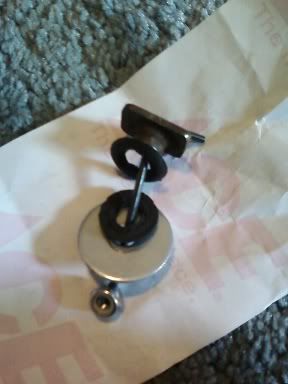
I put everything together and made a few bends to the mounting flange to get the angles right and the light mounted levelly. Here are a few pics along the way. (Side note: I used wing nuts instead of the self locking nuts at this point as they were much quicker to take on and off)
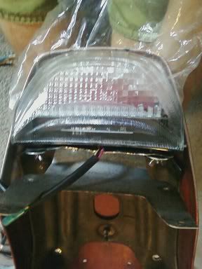
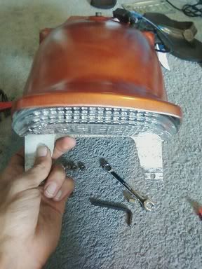
At this point, I noticed that the mounting flanges on the top of the LED light were just coming into contact with the lip on the rear of the fender. I trimmed about 1/4 off of these and it was fine. If I had a dremel, I might have considered taking them off completely to provide a tighter fit.
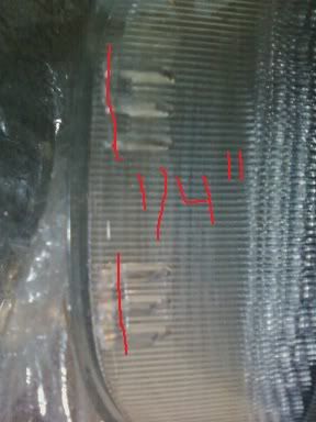
In the final mounting, I also added a bit of clear 3m take to the top of the LED unit to provide additional support. It was rock solid without it, but I figured that it would help keep the tip of the light firmly against the fender. Because of the mounting flanges on the light itself, I had to pile up a few strips of the tape.
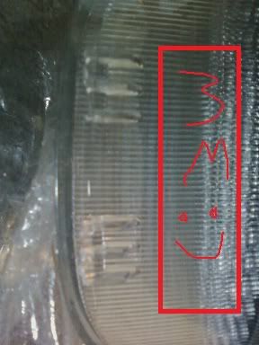
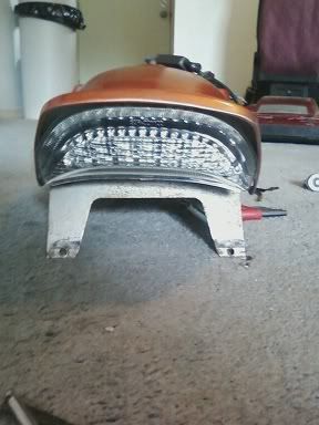
WIRING
I ran the wires along the stock route and connected them to the stock harness connections. The included harness setup is great except for two things, the Honda Style connectors and the length of the wires!
The brake wires are simply too short to reach the Max connections under the passenger seat. I cut the old harness off the stock light and used it as an extension of the LED's brake wires (the three short ones in the white connector). Instead of simply cutting off the connector, I removed it from the pins and used them as crimp type links between the LED and Stock wires.
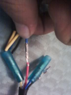
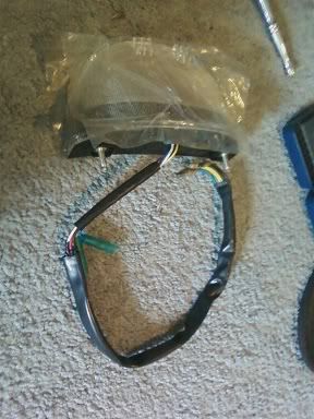
The wires the run from the turn signals to the resistors in the provided harness are, unfortunately, just a few inches to short. I tried to make it fit and ended up having to re-solder a connection that got pulled out. I recommend adding about 4 inches of wire in the connection before the resistors.
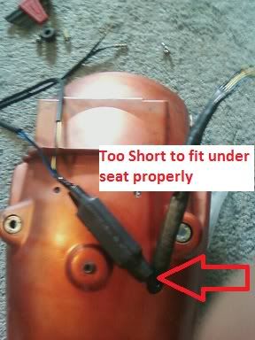
Finally, I took the original ends off of the stock blinkers and added them to the LED wires. This made for an easy final installation on the bike.
Here are a few pics of the fender back on the bike.
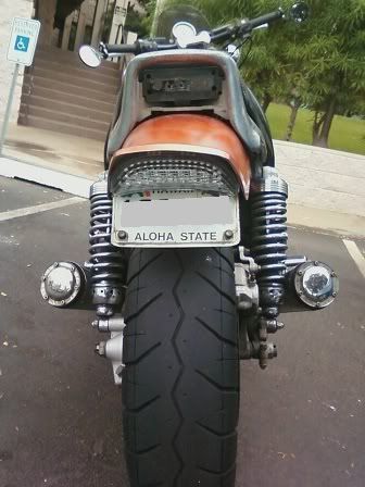
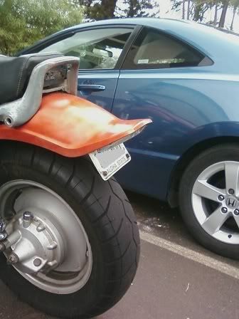
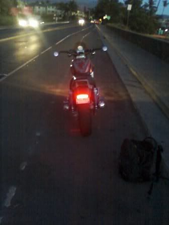
This final picture was taken at dusk. It was still fairly easy to see outside. The light is very bright and visable!!! unk:
unk: unk:
unk:
I hope this gives everyone a possibility of what can be done with this light. Its one of my new favorite things on the Max and was worth every penny.
ask me any questions you might have!
Cheers!

In order to mount this light to the Vmax, there are a few modifications that need to be made to the inner fender. They are fairly simple once you get the idea of what is going on. I did all the metal work with tin snips, pliers, and a drill on the living room floor of my condo. A proper garage setup and some actual tools/metal saw would make this process much more efficient/professional looking!!
Here is a pic of the what the bike looked like when we started. The stickers bellow the plate are for the Hawaii safety check.

The first step is to remove the rear fender and inner fender from the bike. Keep the mounting bolts with you as we will use them during the mock-up as well.
Once the fender is removed, The rear mounts must be removed. *IMPORTANT* Save the square flanged nuts (or whatever they are called) that fit into these mounts. They will be very useful later on.

I used a soldering iron to score along each edge and the broke off very easily. A dremel tool and small cut-off disk would also work well. A sharp knife easily scraped off any remaining bumps.

At this point, I put the new light in the empty fender to see how it would mount.

The mount for the stock mount is about an an inch and a half too far back for the new LED so the old mount must be removed and the inner fender shortened.
I started by cutting slits into either side of the inner fender so about 1/4" past the needed clearance for the new light.


After Cutting the slits, you can also go ahead and cut off the entire section above the rubber grommets for the old light. Bend the entire rear section down 90 Degrees. I did this in reverse order in the pictures and in multiple steps as I kept checking the clearance over the tire.


Once the new flange was bent down, I pounded out the dips in it to make it a straight, flat piece. Then I put it back into the rear fender, and mocked up the new led light. I did this to get an idea of where the holes should be drilled in the flange for the LED mounting bolts to go through. After the holes were drilled, I cut off excess metal on the outside of them. the Final product should look something like this:

For the bolt holes, I believe I used a 5/16 inch drill bit; it seems big, but it must be large enough to fit the spacer with a rubber grommet on it. I will explain this in a bit.
At this point, I began to consider how I was going to mount the rear liscense plate. I like the looks of it under the light, so a new mount was going to have to be added to the inner fender. To this end, I took the Hawaii safety sticker mounting plate and (you can see this under the license plate in the starting picture of the bike up top), bent it up to curve under the light and drilled mounting holes in it and the inner fender.


The double sized hole on the inner fender provides some angle adjustment to the mounting of the plate. I also drilled slots in the license mount (safety sticker thing) to allow for some left to right adjustment. This is what it looked like all together:
From the bottom:

From the back: (Yes yes I know how crappy this all looks, but just keep reading and remember I have no tools or proper work area!)

Now its time to make sure the angle of the mounting flange is correct to position the light in the fender.
Attach the inner fender to the fender using the mounting bolt to line everything up.

Now how are we going to actually bolt in the light? The bolts coming out of the unit are a little skinny and don't mount to a flat surface as they have a section of plastic around them.

Remember those mounting nuts I told you to save out of the rear light mounts on the fender? It turns out that they fit perfectly (after grinding 1/16 of an inch off of the inner sides

They will provide an even mounting pressure on the light and work perfectly to hold a rubber grommet. This will give the light a small amount of vibration insulation from the inner fender. (Its how the original was installed so I figured it would be good to copy!)
Here is a picture of the mounting hardware I used. I believe the grommet was 5/16 inside diameter. It just stretched a bit to fit over the square spacer.

I put everything together and made a few bends to the mounting flange to get the angles right and the light mounted levelly. Here are a few pics along the way. (Side note: I used wing nuts instead of the self locking nuts at this point as they were much quicker to take on and off)


At this point, I noticed that the mounting flanges on the top of the LED light were just coming into contact with the lip on the rear of the fender. I trimmed about 1/4 off of these and it was fine. If I had a dremel, I might have considered taking them off completely to provide a tighter fit.

In the final mounting, I also added a bit of clear 3m take to the top of the LED unit to provide additional support. It was rock solid without it, but I figured that it would help keep the tip of the light firmly against the fender. Because of the mounting flanges on the light itself, I had to pile up a few strips of the tape.


WIRING
I ran the wires along the stock route and connected them to the stock harness connections. The included harness setup is great except for two things, the Honda Style connectors and the length of the wires!
The brake wires are simply too short to reach the Max connections under the passenger seat. I cut the old harness off the stock light and used it as an extension of the LED's brake wires (the three short ones in the white connector). Instead of simply cutting off the connector, I removed it from the pins and used them as crimp type links between the LED and Stock wires.


The wires the run from the turn signals to the resistors in the provided harness are, unfortunately, just a few inches to short. I tried to make it fit and ended up having to re-solder a connection that got pulled out. I recommend adding about 4 inches of wire in the connection before the resistors.

Finally, I took the original ends off of the stock blinkers and added them to the LED wires. This made for an easy final installation on the bike.
Here are a few pics of the fender back on the bike.


This final picture was taken at dusk. It was still fairly easy to see outside. The light is very bright and visable!!!

I hope this gives everyone a possibility of what can be done with this light. Its one of my new favorite things on the Max and was worth every penny.
ask me any questions you might have!
Cheers!




![Bovemanx Motorcycle Phone Mount Holder, [150mph Wind Anti-Shake][7.2inch Big Phone Friendly] Bike Phone Holder, Motorcycle Handlebar Cell Phone Clamp, Compatible with iPhone 16 Pro Max Smartphones](https://m.media-amazon.com/images/I/51F+1sontPL._SL500_.jpg)


![Lamicall Motorcycle Phone Mount Holder - [Dual Vibration Dampener] [720° Adjustment Arm] Motorcycle Cell Phone Holder, Bike Handlebar Phone Mount, for iPhone 16/15/ 14/13 Pro Max, 4.7-6.7" Phones](https://m.media-amazon.com/images/I/41g9IDInCIL._SL500_.jpg)


