


naughtyG
Well-Known Member
I wasn't impressed with the OEM horn on my V-Max - it sounded more like a 50cc moped or scooter than a 1200cc Muscle Bike to me!
So I set out to get a more appropriate sound, and here's how I went about it:
Looking on fleaBay, I found this seller that listed a pair of chrome Air Horns for $15 with Free Shipping - nice! :eusa_dance:


Here's the picture in the listing (item No 320309363873):
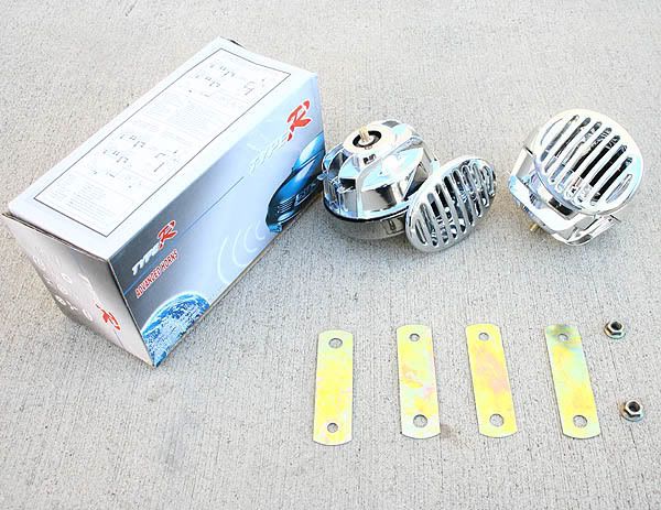
They arrived promptly, and exactly as described. Nice cheapo aftermarket chrome plastic items - if they break I can replace them easy - and $15 ain't braking the bank :biglaugh:
I started by unplugging and removing the offending item with its bracket - let's see if I can get my $15 back by flogging it on the Bay LOL :rofl_200:

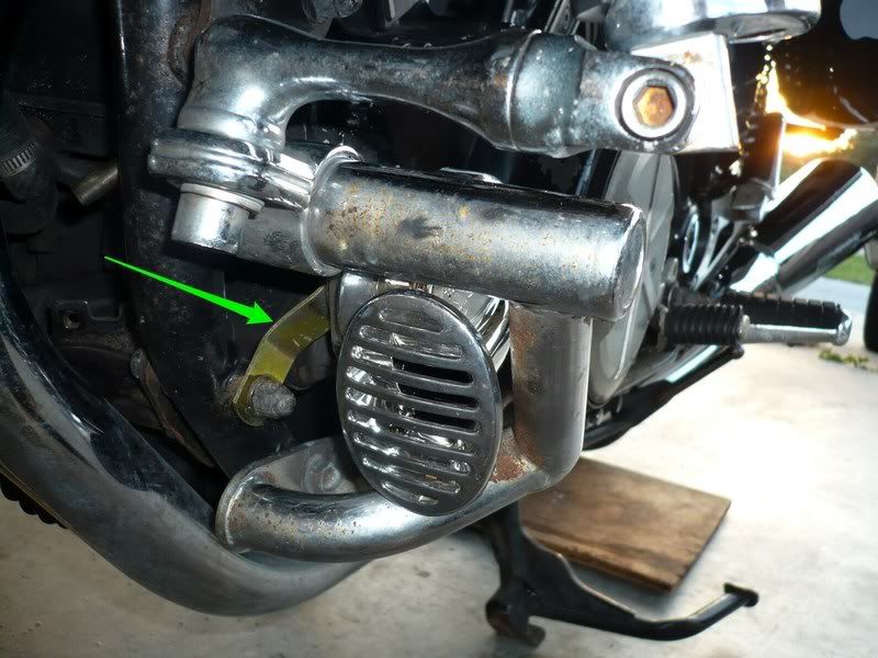
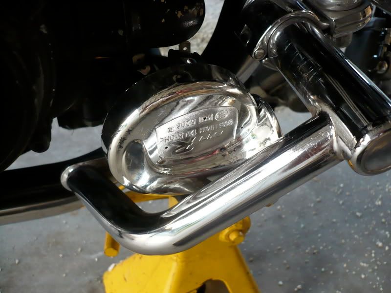
I mounted the new horns inside the engine guards, using an existing bolt, and using the brackets supplied with the horns. I suitably bent those brackets (using a pair on each side) so that the horns would fit perfectly in the available space.
Here's the left horn in place, with the bent bracket arrowed. You can also see the holes the OEM horn bracket used to fit in to the left.
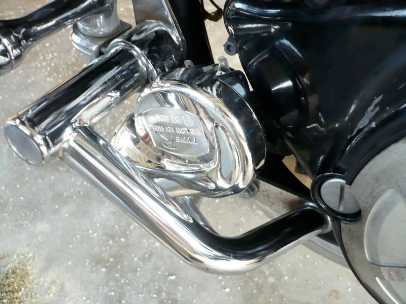
Side view of the left horn:
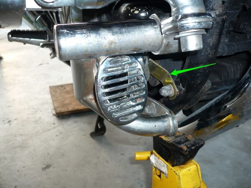
Right horn mounted with the bent to shape bracket arrowed:
And a side view of the right horn:
Next I removed the faux-tank cover, and also both left and right scoops.
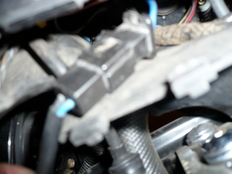
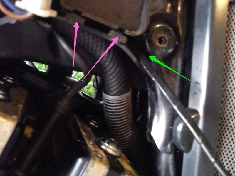
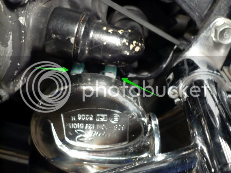
Under the left scoop, I unhooked the two relays by lifting them up off their metal tabs (pink arrows) and unscrewed the V-boost controller (green arrow) - no need to unplug any of their connectors!
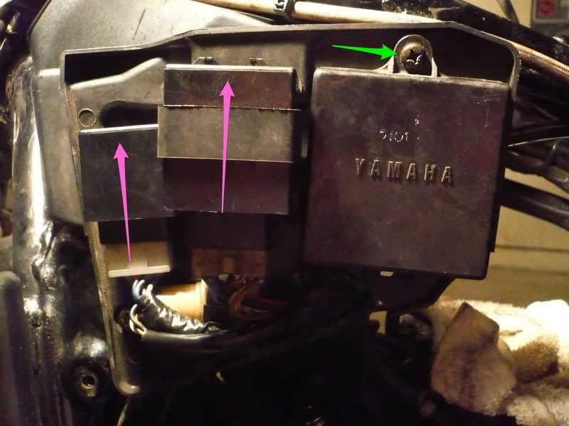
Then I removed the round valve/relay (not sure what it is!:ummm") from its bracket (pink arrow) and then fed all the wires (green arrow) out of the slot they come through and let all those items hang down for now.
from its bracket (pink arrow) and then fed all the wires (green arrow) out of the slot they come through and let all those items hang down for now.
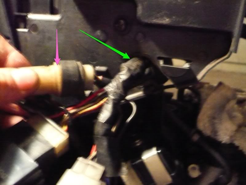
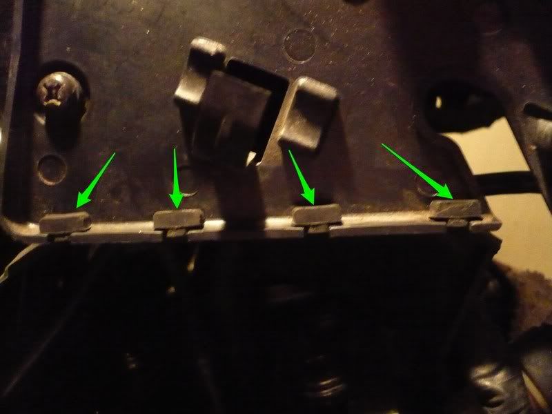
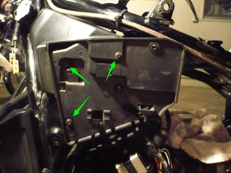
I pulled the four rubber tabs (green arrows) off the heat shield
disconnected my cooling fan connector
then removed the whole panel (3 screws arrowed) to expose the wiring harness. You may notice that my airbox and carbs are also missing - I'm in the process of cleaning them, but them being in place would make no difference to this mod.
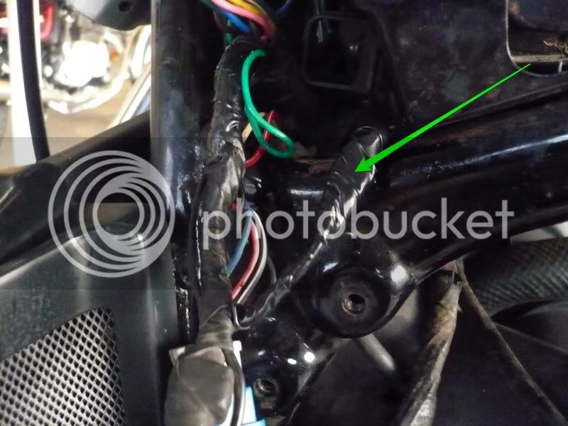
next I pulled out the arrowed relay from its housing
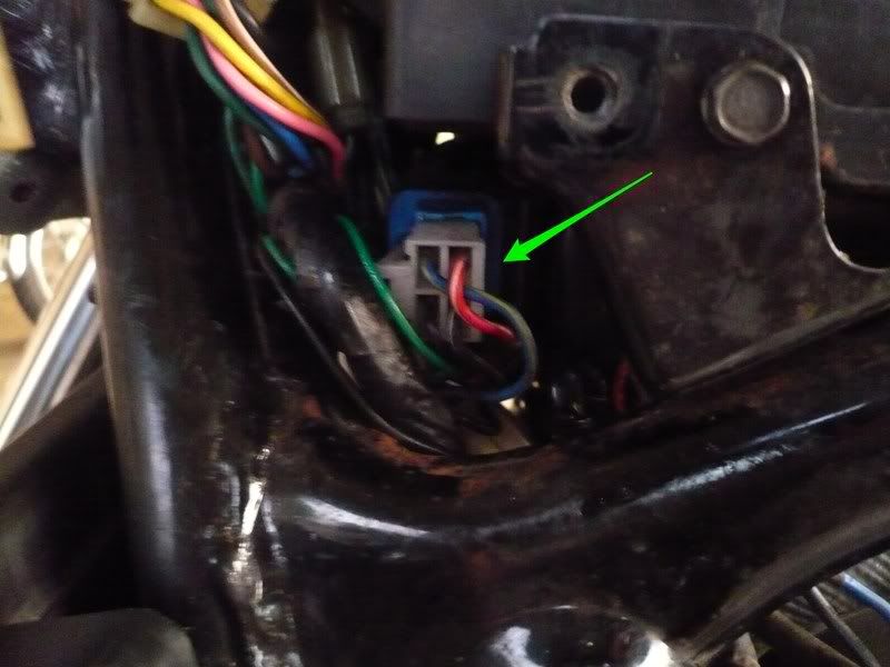
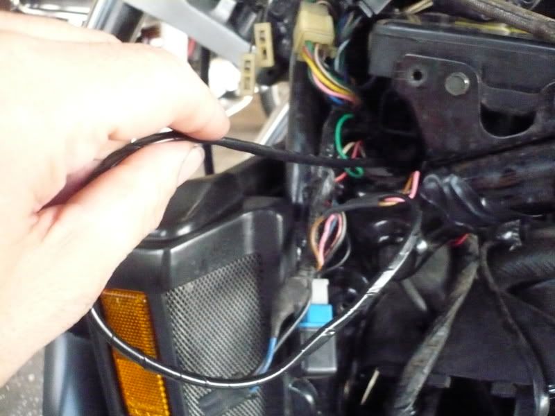
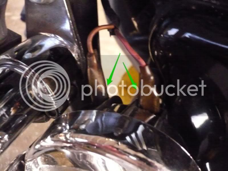
and this allowed me to pull out the wiring harness (green arrow) enough from behind the frame tubes to expose the horn wires (pink arrows) - I traced these up from the horn - they run up the left frame tube and join the harness here. You'll need to feed the horn wires up a bit through their metal hooks to have enough slack to pull it all out. On my '86, the horn wires are Brown and Pink.
Then I cut the horn wires (green arrows), to ready them to be tinned for solder and splice:
I prepared my new wires for the second horn by cutting them to an appropriate length and taping them together with black electrical tape. (got this appropriate gauge black electrical wire from Home Depot for about $3, and have loads left over) Notice one end already tinned and ready to solder:
Soldered the original wires back together with the new ones spliced on - yes you need a lot of fingers to get this right..unk: The new wires are arrowed in green, and notice the pink arrows pointing at the heat shrink sleeves put in place before soldering
Time to borrow wifey's hair dryer and do some shrinking, having checked the soldering was good and solid..
Next I fed the new wiring across to the other side:
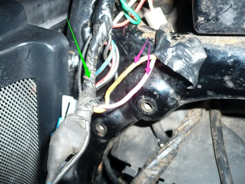
If you look thru you can actually see a passage across! (arrowed in green)
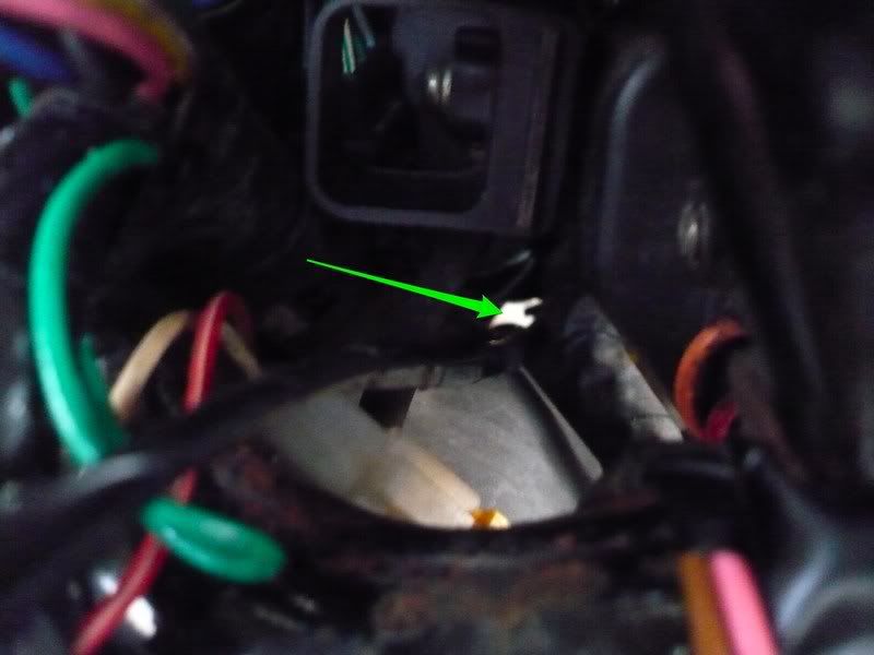
This is where it comes out on the right side (green arrow). The pink arrows show the heat shield rubber tabs I unhooked to open the passage for the wires.
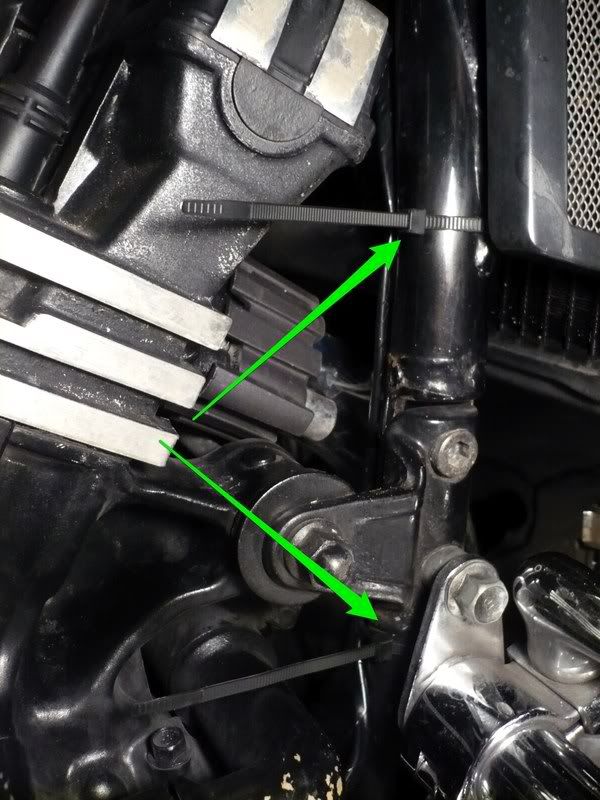
Next I secured the new wiring to the right frame tube with a couple of cable ties (arrowed), making sure it's clear from any hot parts.
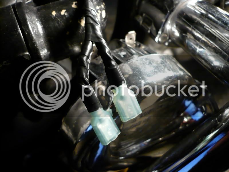
Here's the new wiring out by the right horn, trimmed to length and ready to be dealt with
Same wires with crimped on isolated spade connectors, and all taped up and ready:
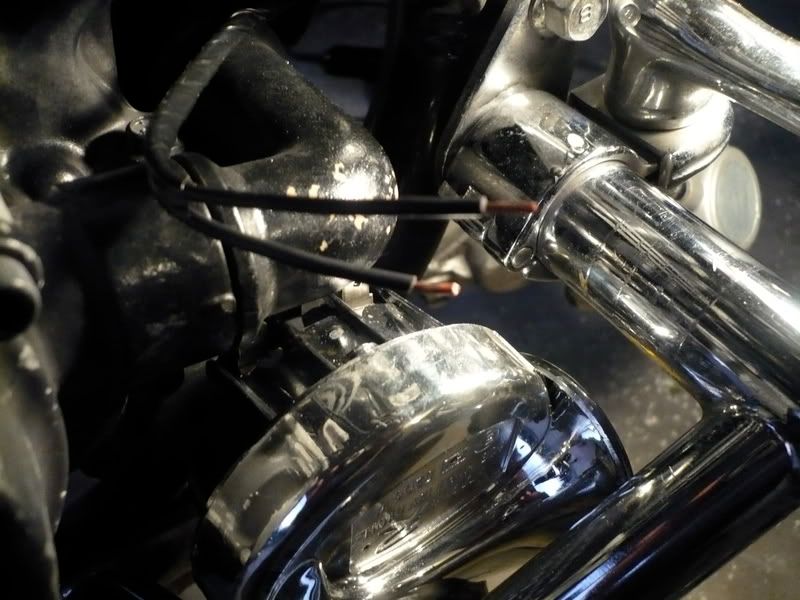
Right horn is now connected. Notice how I had to bend the horn's spades (green arrows) to clear the coolant elbow:
The left horn is connected using the original wiring:
The spliced horn wires (green arrow) all taped up and ready to be fed back behind the frame:
Then refitting was simply a reversal of removal. Once the wires were back in place, I refitted the (V-boost?) relay, the left plastic panel with its 3 screws, reconnected the cooling fan, rehooked the rubber tabs on both sides, fed the relays and V-boost controller's harness through the slot in the left panel, reattached the unknown(!) round valve/relay, reattached both relays and V-boost controller, and finally refitted the cowls and faux-tank cover.
And here's the result of the dual horns mod:
First a picture of both horns mounted (the front wheel is off for new bearings..) - notice the BLING factor :rofl_200::rofl_200::rofl_200:
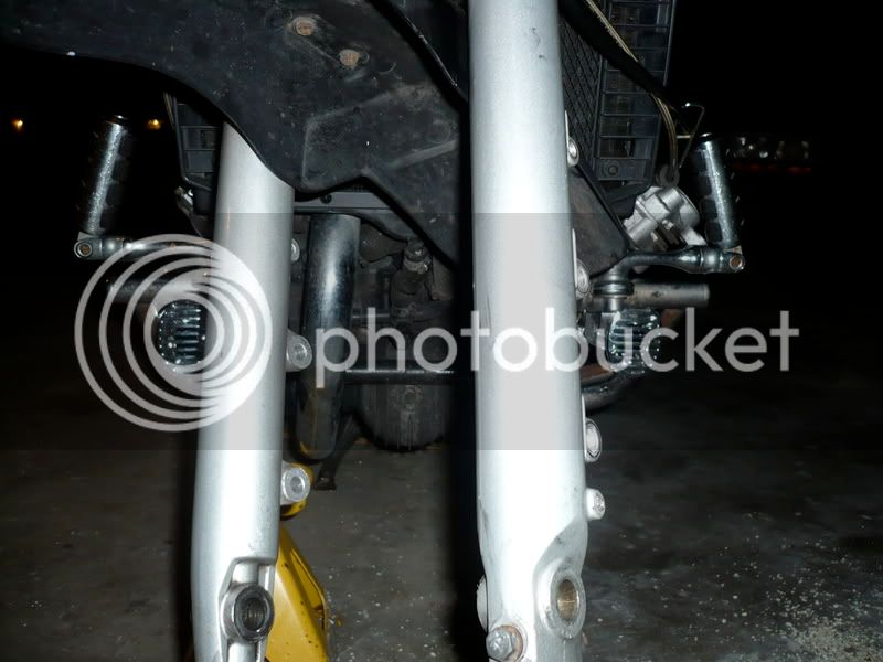
And finally, this whole thread would be useless without the sonic result of the mod - I really like it as Maxine now sounds a lot more like its weight - these things are LOUD and the 2-tone dual horns are reminiscent of a large luxury car. When I sound these, other road users WILL pay attention!!!
(Don't forget to turn your speakers up ALL THE WAY to get the full effect :clapping
http://uk.youtube.com/watch?v=iS1V71151_o
So I set out to get a more appropriate sound, and here's how I went about it:
Looking on fleaBay, I found this seller that listed a pair of chrome Air Horns for $15 with Free Shipping - nice! :eusa_dance:
Here's the picture in the listing (item No 320309363873):
They arrived promptly, and exactly as described. Nice cheapo aftermarket chrome plastic items - if they break I can replace them easy - and $15 ain't braking the bank :biglaugh:
I started by unplugging and removing the offending item with its bracket - let's see if I can get my $15 back by flogging it on the Bay LOL :rofl_200:
I mounted the new horns inside the engine guards, using an existing bolt, and using the brackets supplied with the horns. I suitably bent those brackets (using a pair on each side) so that the horns would fit perfectly in the available space.
Here's the left horn in place, with the bent bracket arrowed. You can also see the holes the OEM horn bracket used to fit in to the left.
Side view of the left horn:
Right horn mounted with the bent to shape bracket arrowed:
And a side view of the right horn:
Next I removed the faux-tank cover, and also both left and right scoops.
Under the left scoop, I unhooked the two relays by lifting them up off their metal tabs (pink arrows) and unscrewed the V-boost controller (green arrow) - no need to unplug any of their connectors!
Then I removed the round valve/relay (not sure what it is!:ummm
from its bracket (pink arrow) and then fed all the wires (green arrow) out of the slot they come through and let all those items hang down for now.
I pulled the four rubber tabs (green arrows) off the heat shield
disconnected my cooling fan connector
then removed the whole panel (3 screws arrowed) to expose the wiring harness. You may notice that my airbox and carbs are also missing - I'm in the process of cleaning them, but them being in place would make no difference to this mod.
next I pulled out the arrowed relay from its housing
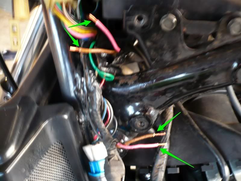
and this allowed me to pull out the wiring harness (green arrow) enough from behind the frame tubes to expose the horn wires (pink arrows) - I traced these up from the horn - they run up the left frame tube and join the harness here. You'll need to feed the horn wires up a bit through their metal hooks to have enough slack to pull it all out. On my '86, the horn wires are Brown and Pink.
Then I cut the horn wires (green arrows), to ready them to be tinned for solder and splice:
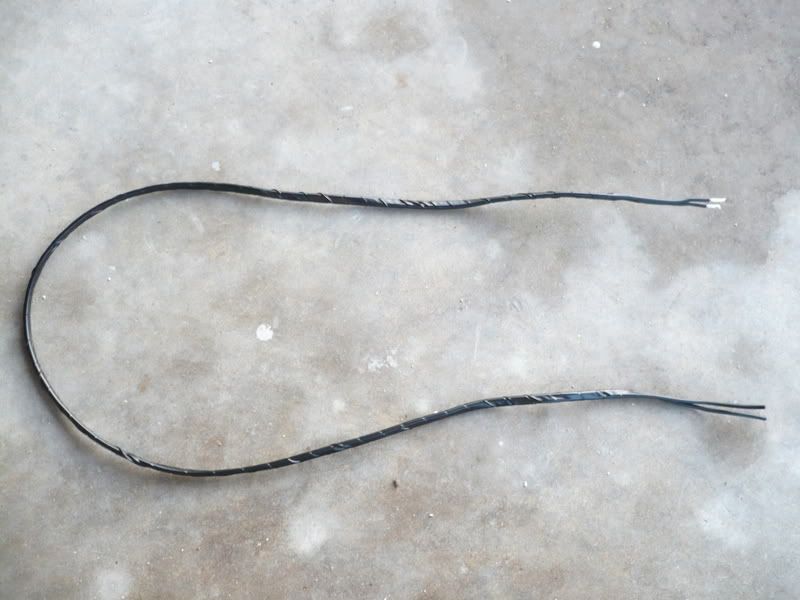
I prepared my new wires for the second horn by cutting them to an appropriate length and taping them together with black electrical tape. (got this appropriate gauge black electrical wire from Home Depot for about $3, and have loads left over) Notice one end already tinned and ready to solder:
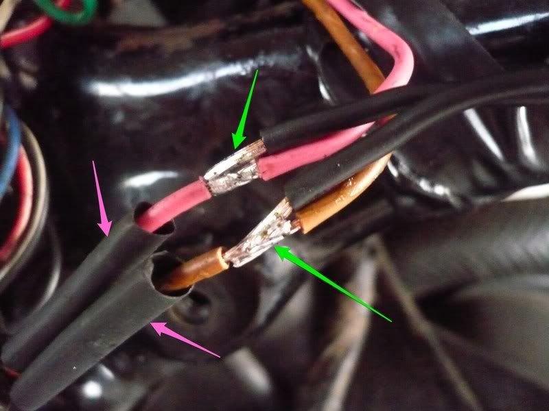
Soldered the original wires back together with the new ones spliced on - yes you need a lot of fingers to get this right..
unk: The new wires are arrowed in green, and notice the pink arrows pointing at the heat shrink sleeves put in place before soldering
Time to borrow wifey's hair dryer and do some shrinking, having checked the soldering was good and solid..
Next I fed the new wiring across to the other side:
If you look thru you can actually see a passage across! (arrowed in green)
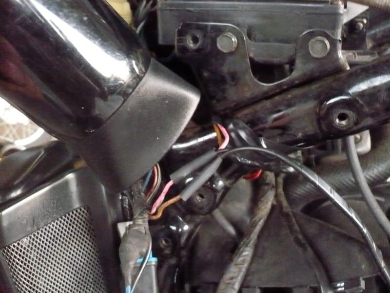
This is where it comes out on the right side (green arrow). The pink arrows show the heat shield rubber tabs I unhooked to open the passage for the wires.
Next I secured the new wiring to the right frame tube with a couple of cable ties (arrowed), making sure it's clear from any hot parts.
Here's the new wiring out by the right horn, trimmed to length and ready to be dealt with
Same wires with crimped on isolated spade connectors, and all taped up and ready:
Right horn is now connected. Notice how I had to bend the horn's spades (green arrows) to clear the coolant elbow:
The left horn is connected using the original wiring:
The spliced horn wires (green arrow) all taped up and ready to be fed back behind the frame:
Then refitting was simply a reversal of removal. Once the wires were back in place, I refitted the (V-boost?) relay, the left plastic panel with its 3 screws, reconnected the cooling fan, rehooked the rubber tabs on both sides, fed the relays and V-boost controller's harness through the slot in the left panel, reattached the unknown(!) round valve/relay, reattached both relays and V-boost controller, and finally refitted the cowls and faux-tank cover.
And here's the result of the dual horns mod:
First a picture of both horns mounted (the front wheel is off for new bearings..) - notice the BLING factor :rofl_200::rofl_200::rofl_200:
And finally, this whole thread would be useless without the sonic result of the mod - I really like it as Maxine now sounds a lot more like its weight - these things are LOUD and the 2-tone dual horns are reminiscent of a large luxury car. When I sound these, other road users WILL pay attention!!!
(Don't forget to turn your speakers up ALL THE WAY to get the full effect :clapping
http://uk.youtube.com/watch?v=iS1V71151_o


![Bovemanx Motorcycle Phone Mount Holder, [150mph Wind Anti-Shake][7.2inch Big Phone Friendly] Bike Phone Holder, Motorcycle Handlebar Cell Phone Clamp, Compatible with iPhone 16 Pro Max Smartphones](https://m.media-amazon.com/images/I/51F+1sontPL._SL500_.jpg)


