Integrated CBR LED Tail Light Mounting

VMAX  Forum

Help Support VMAX Forum:

This site may earn a commission from merchant affiliate links, including eBay, Amazon, and others.
Ninjaneer,

Sounds like a bad earth.
I'm not a sparky, but ...
- adding a resistor to the indicators means that they are not running on 12v now.
- if you have resistance on the earth connection, then by turning on the taillight you will create a slightly positive earth. (Think of the electrons not being able to get to the chassis)
-Therefore with the taillight on, there may not be enough voltage difference between "earth" and "12v positive" to make the indicators work.

Maybe try a good earth?
Or maybe even a resistor on the taillight!
 
Is your battery in good shape? Sometimes that causes issues as well. My brother's battery is on its way out and his will hyper flash every now & then at idle.
ya the battery is in good shape--holding 12.8 volts last time i measured with the bike off, but your question and points may have some merit in my case. i will elaborate after addressing baz's points

Ninjaneer,
Sounds like a bad earth.
I'm not a sparky, but ...
- adding a resistor to the indicators means that they are not running on 12v now.
- if you have resistance on the earth connection, then by turning on the taillight you will create a slightly positive earth. (Think of the electrons not being able to get to the chassis)
-Therefore with the taillight on, there may not be enough voltage difference between "earth" and "12v positive" to make the indicators work.

Maybe try a good earth?
Or maybe even a resistor on the taillight!

so here's the thing, the turn and running lights share the same earth access via the one ground wire that comes out of the taillight fixture. to make sure the fixture still functioned normally, i connected this ground wire to the earth bolt on the frame and turn and running wires directly to the battery this worked. however, after reading your points, i realized that when i hooked in the load resistor, i didn't ground it to the frame, but rather to one of the ground wires in the back. so i just got back from trying out ground the resistor to the frame bolt. no joy. but i think you are about the turn signals not getting enough voltage and that the load resistor is introducing an ill side effect. also, sorry for being nit-picky but the electrons won't ever be able to get to the chassis, because electrons flow in the opposite direction, from negative to positive, than that of the physical electrical current which flows from the positive to the negative pole.


so grimmie and baz, this is what i think is going on. the turn signal voltage looks good when measured coming out of the flasher, the handlebar switch pod, and into the front led. however, it is somewhat low (10.something volts) when it is measured at the connection in the rear. this more than likely is the result of load resistor that i have on the front turn signal. adding another load resistor drops the voltage even further. i cannot rely on the fact that the battery will charge up to 13.9 volts while the bike is running (i measured it the other month and the battery is only a few months old), because of the thing that started it all--my wife was tailing me and criticized me why i didn't use my turn signals. dropping the front turn signal's resistor down from 10 ohms to 7.5 didn't help matters and going back and forth to and from the electronics store is a hassle.

rather, i think my best recourse is to introduce these relays, which energize at 3 volts and provides a cleaner, stronger, battery voltage via the running light. the crappy turn signal voltage is no longer a factor because if it ever goes below 3 volts, i would say i have bigger eggs to fry. i thought about hooking the relays' 30 terminals straight to the battery, but then i would have to add another relay that would "normally" disconnect the previous relay when the bike was off. right now the running light wire seems to be a good enough source.
 
Dude, I've got it all wrong!

Assuming you have wired the resistors like this picture, there will be NO voltage drop caused by the resistors. My assumption of the resistors being in series was LAME, and not how it should be done.

If you measure the voltage at the lights it should be battery voltage.

If you are getting battery voltage at the front signals, but not at the back signals, then it's a problem in the loom.

Before you go extreme with the relays, maybe try connecting the rear signals directly to the front ones with 2 long wires, and see if that works. That would get rid of the voltage drop.

If that works, the fix will be much easier and neater. Just run new positive wires to the rear signals. :biglaugh:

Sorry about the electron comment. Was just talking 'conventional' current, as most people understand it. You sound like you have had enough of this job! I wish I could help more!
 

Attachments

  • Resistor_wiring_diagram.png
    Resistor_wiring_diagram.png
    49.4 KB · Views: 88
Dude, I've got it all wrong!

...Before you go extreme with the relays, maybe try connecting the rear signals directly to the front ones with 2 long wires, and see if that works. That would get rid of the voltage drop.

If that works, the fix will be much easier and neater. Just run new positive wires to the rear signals. :biglaugh:

great idea baz! went out and tried it. no joy:confused2:. ya i'm at a loss as to what is the root cause. i hate to throw in some more relays, but they make the lights work. it is like what we call at work "a band-aid" fix, something that is frowned upon because it doesn't fix the real problem, but rather covers it up giving the appearance of a nominally working system.

don't apologize, about the electron thing. i should be the one apologizing. i don't know what possessed me to submit such a retort. i guess this issue is truly rubbing me the wrong way.

i really do appreciate all of your suggestions and help. but like you said, i'm fed up with this problem and just want to get out on the road. it has been absolutely gorgeous the past few days and the bikes sitting in the garage with its entrails splayed out all over the place.
30.gif
 
Man, that sucks!

If the resistors are in parallel, not series, then I'm stumped.
Like that, the resistor make no difference to the voltage at the light. It just creates more load to change the flashing rate. If it works with no resistor it should work with one. Grrrr.

If the taillight disconnected makes the signals work, then the only things shared by those lights is the earth. You've checked the earth. It's not that.

The only thing that hasn't been mentioned is try another flasher unit.

Gosh, what a pickle.

Maybe just use 1 relay for each side signal, using 2 load resistors in parallel, and connected to both signal lights. That would reduce the parts count of your work-around. 2 less relays.

Sorry I couldn't help more!
 
Oh, I'm only planning on using two relays total--one for each rear turn indicator wire. I did try a different flasher. I, up until I put the cbr light in, had been using a Custom Dynamics flasher with favorable results. Putting it back in was one of the first things I tried. :-(

Thanks again for you time and contrary to what may think, you HAVE been helpful!!!

regards from my tapatalking android...
 
Defenitivly a fkn good idea

i`m already on LED mod that i did my own, it keep`s the theme of my bike but not bright enought

this mod is for me, i go on with`in the next days

thank you,
 
What's everyone buying, the clear or smoked lense?

I like the look of the smoked, but want to make sure that it is bright enough.
 
How much was it? They are both the same price now.
i wondered myself and went back and had a look at my records. it all came back to me. i was mistaken when i said "it wasn't on sale". the eBay vendor was only selling the clear one. the purchase totaled something like $54 plus $8 shipping, but i had some eBucks, which brought my total out-of-pocket down to something like $48. unfortunately, i had to buy a couple of relays (as you may have noticed from my earlier posts) and the epoxy. so grand total of the project was something like $65.
 
Just got mine in from Motodynamic yesterday and installed it similarly to the way Grimmie did his. I can't say enough about how much better this looks over the ugly-ass factory tail light. Not to mention the that the flash warning brake signal is pretty cool. Thanks to everyone for contributing to this thread. My wife complained when I told her that I was ordering a new tail light. "65 bucks? But the one on it is working fine." After seeing it done she said, "Ok, it was worth it. Now that I see this one, I realize how ugly the old one was." When I can get the wife's approval, it's definitely worth it.
 
My old lady had the same reaction after hassling me with the same business. ha ha ha! Congrats!

Sent from my Tapatalking Hercules Android
 
I just finished doing this upgrade yesterday. I did the tape and epoxy mount and it went very well. The only thing I had an issue was with testing it out - the brake worked well but only 1 blinker would work. After tearing into everything and almost giving up, I remembered that every video I'd seen showed the bike running. Started it up and everything worked just like it should. Best $60 I ever spent!
 
Yha, this was one of my better 60$ spend to

It seems that will see a lot of CBR bad ass:biglaugh:

My friend say that it look factory made:clapping:
 
There is a $10 coupon good only for Memorial Day.

Todd


Enter coupon code: MEMORIAL10 at checkout to receive $10 off your purchase of any Sequential LED Tail Light.

Offer valid May 28, 2012 12:00AM -11:59PM EST*
 
I installed the CBR tail light setup and did it the same as everyone else with a little different fabrication to the inner fender support.

Here are some pictures.

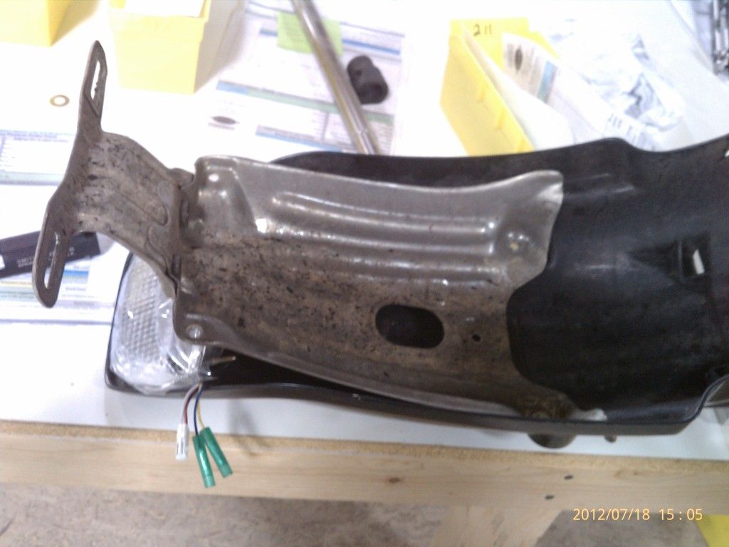
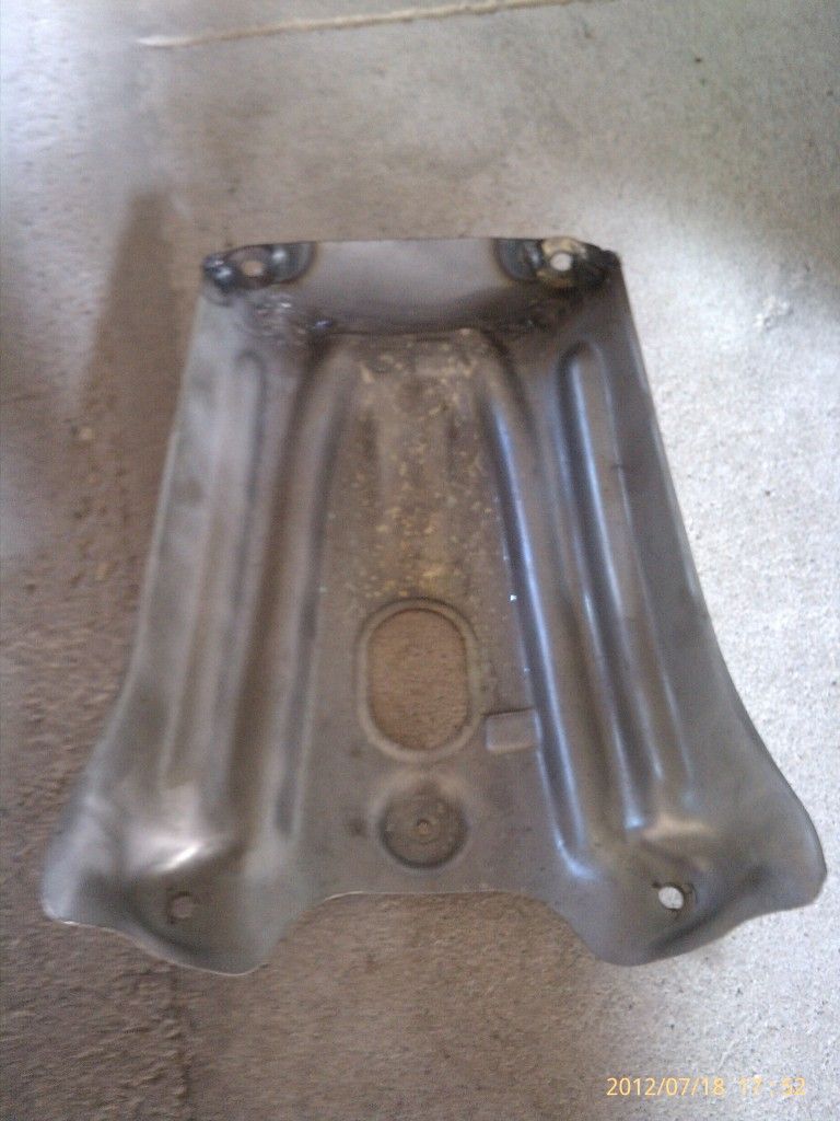
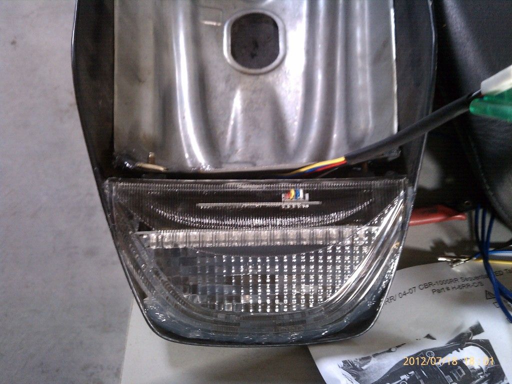
Here is the fender as it is stock pulled right off the bike. I have the CBR light underneath it for mock up.

IMAG0996.jpg


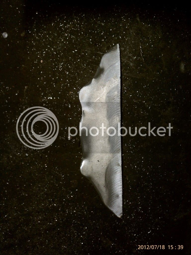
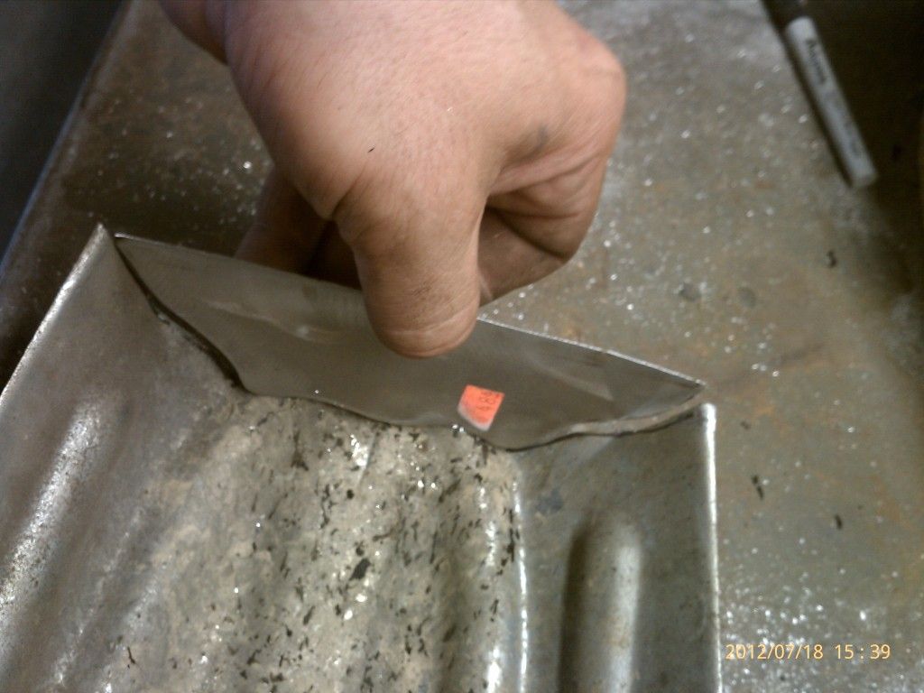
Here I cut the back end off just before the CBR tailight.

IMAG0997.jpg


IMAG0998.jpg


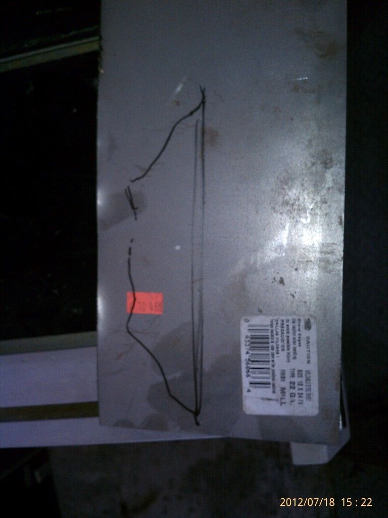
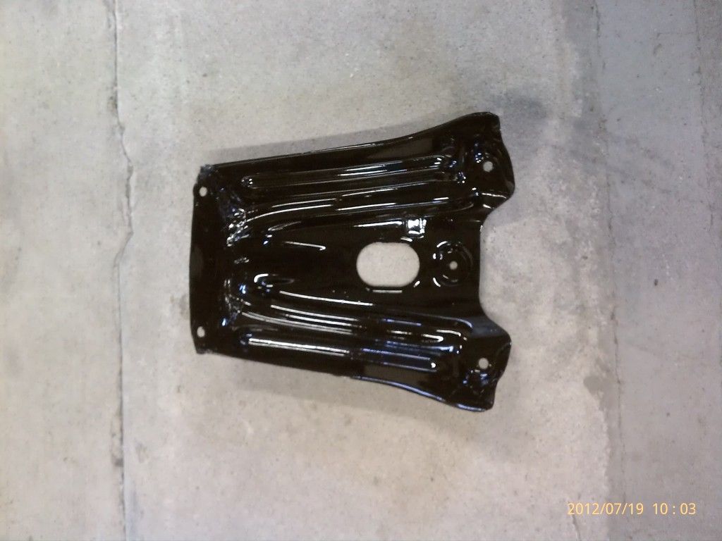
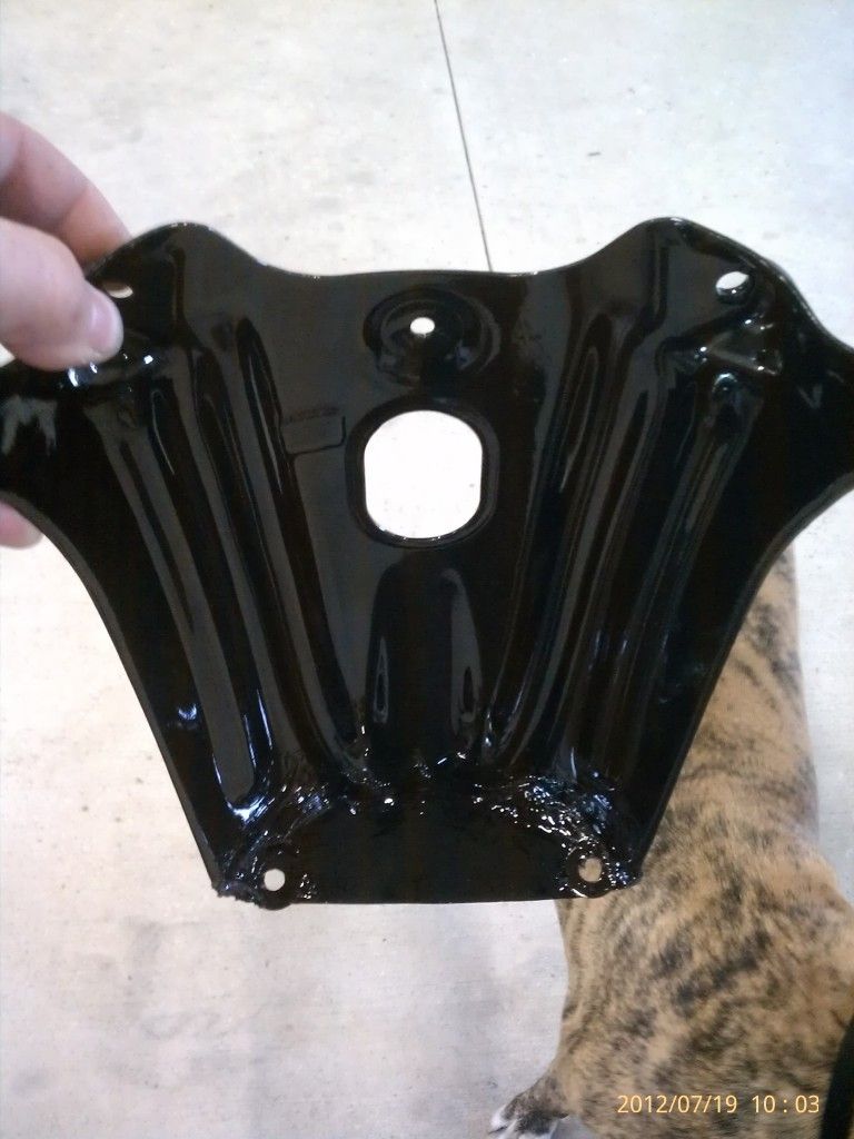
Next is a back plate I made from scrap 22 gauge sheet metal I have laying around.

IMAG1001-1.jpg

IMAG1002-1.jpg

IMAG1003-1.jpg


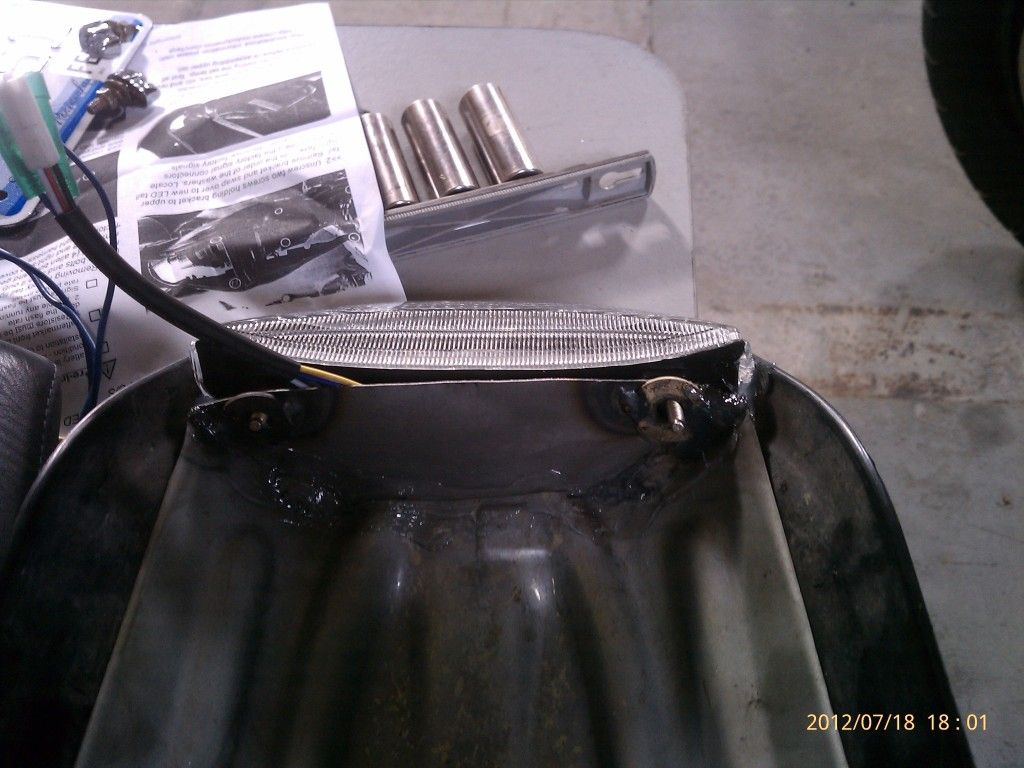
I tig welded it in place and welded a couple washers in place as I made a mistake on my hole location originally.

IMAG1006-1.jpg


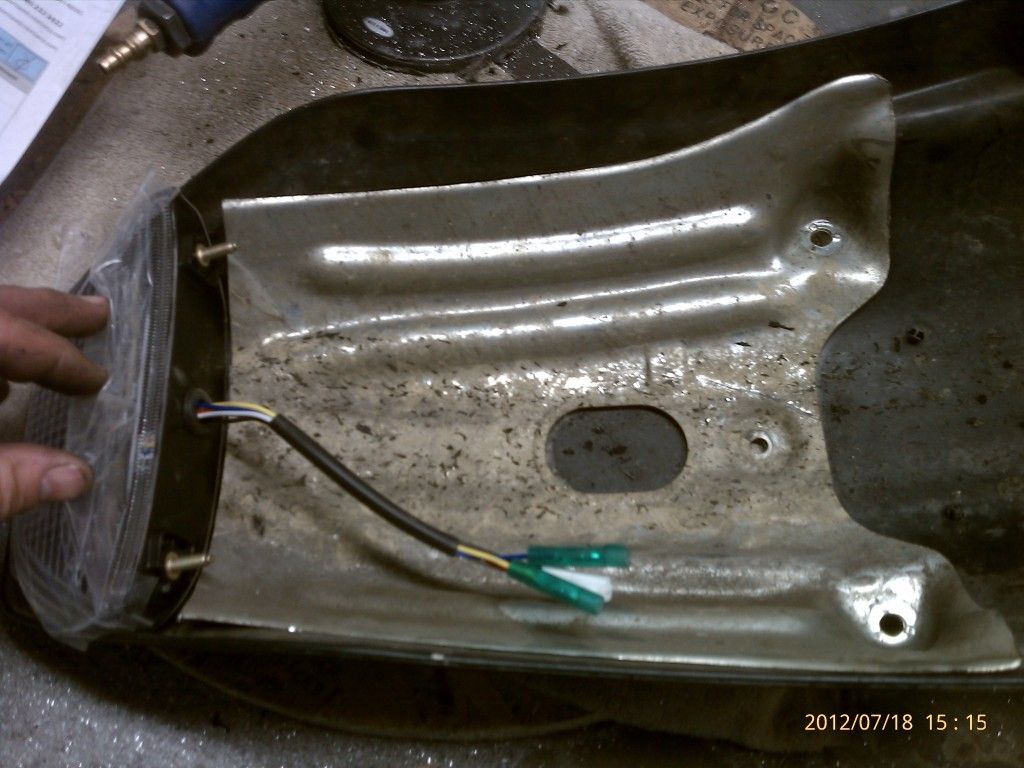
Here its sitting in place, again mocking it up.

IMAG1010-1.jpg


As you can see I siliconed the tail light in place. Its in there good and tight. No way that sukcers coming off.

IMAG1011-1.jpg


I then powder coated it mirror black so it was easy to clean the burnt rubber off it.....:biglaugh:

IMAG1017-1.jpg


Yes I siliconed the entire inside to keep it from spraying water through the back plate. And yes I powder coated over the silicone and suprisingly it worked out good.

IMAG1019-1.jpg


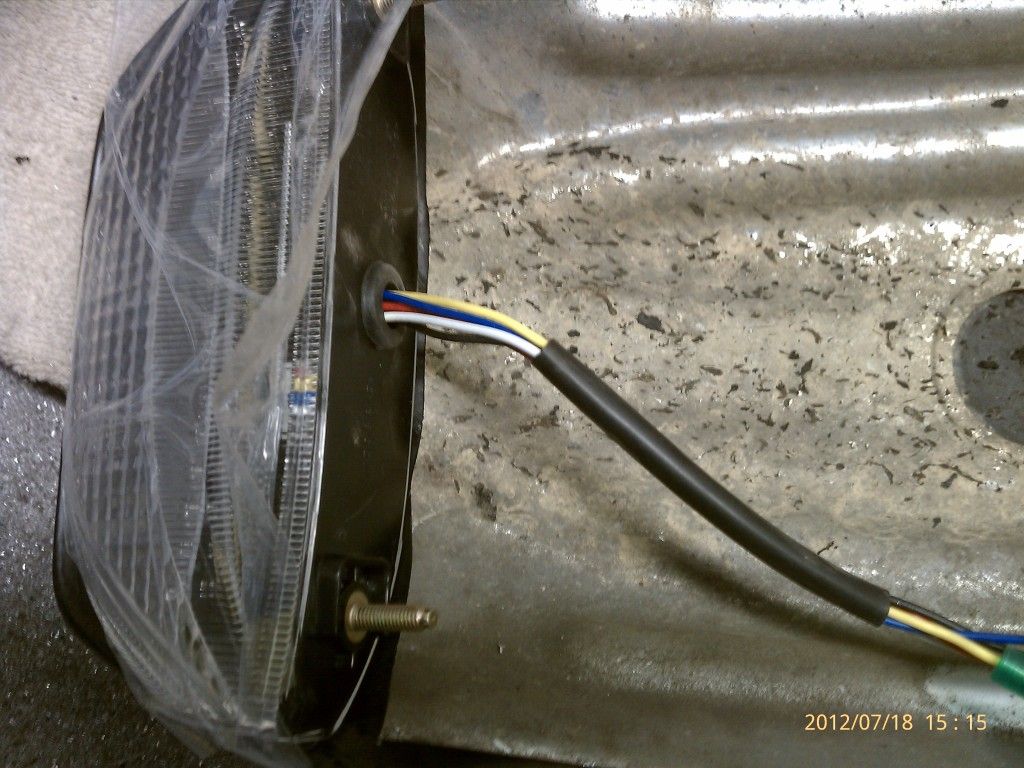
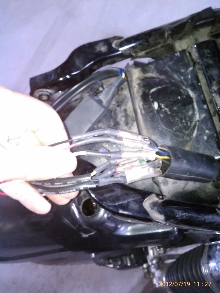
Not a very good picture. But I shrink wrapped all my connections and used bullet connectors to attached everything like it was factory.

IMAG1027-1.jpg


Here we are all wrapped up. I sandwiched the plate between the back splash of the inner fender and the two screw studs for the tail light. I put a piece of 1/8 rubber strip between the tail light and the license plate and then tightened the tail light to the back splash.

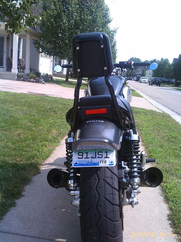
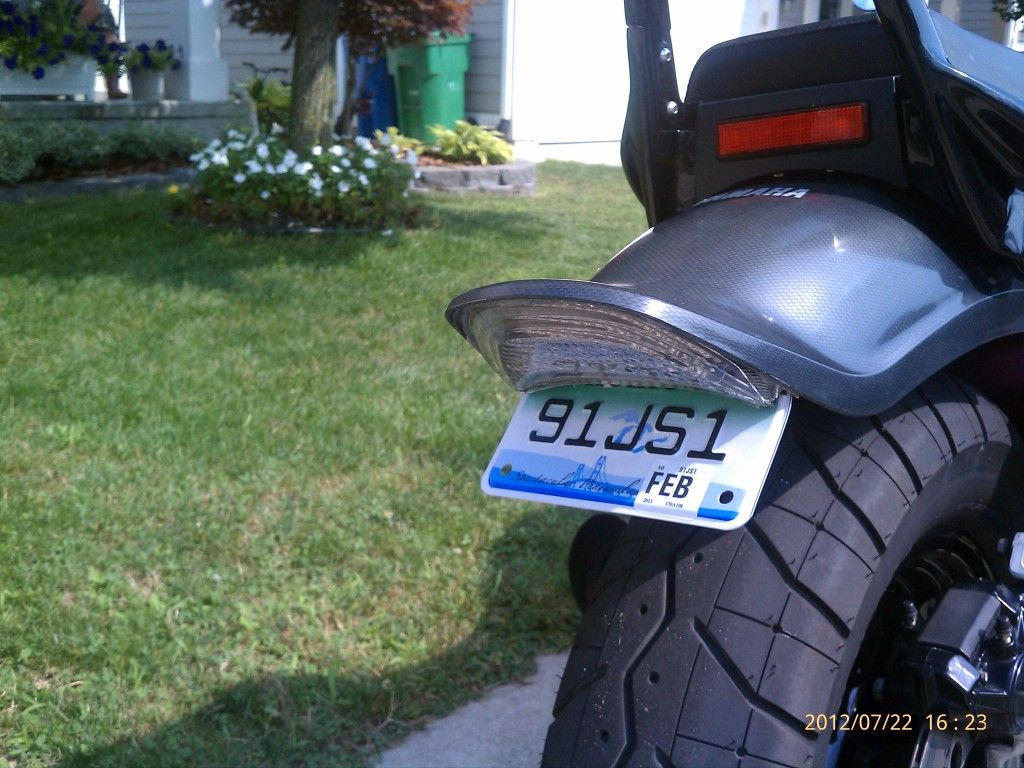
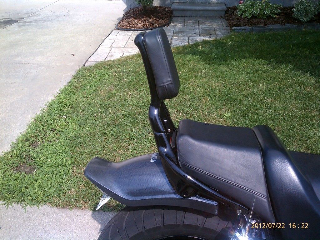
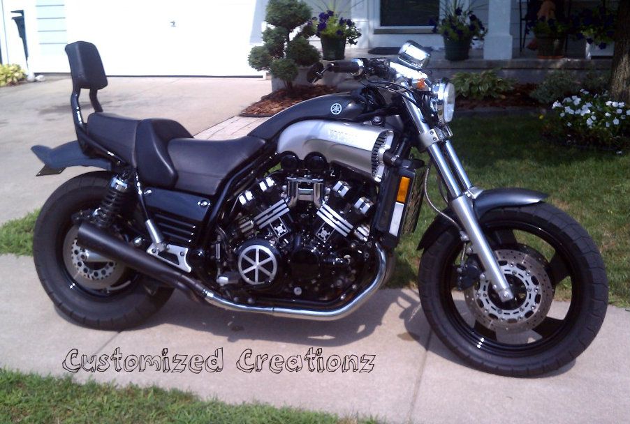
Here is the finished product.

IMAG1076.jpg

IMAG1077.jpg

IMAG1075.jpg


Vmax7-20-2012.jpg


I bought the light off ebay. It was $65 shipped. Everything was pretty much plug and play. It wired right in and I also installed two led's I had laying around in the reflector, so it now lights up also when the brake light is activated.

Thanks
Todd
 
Back
Top