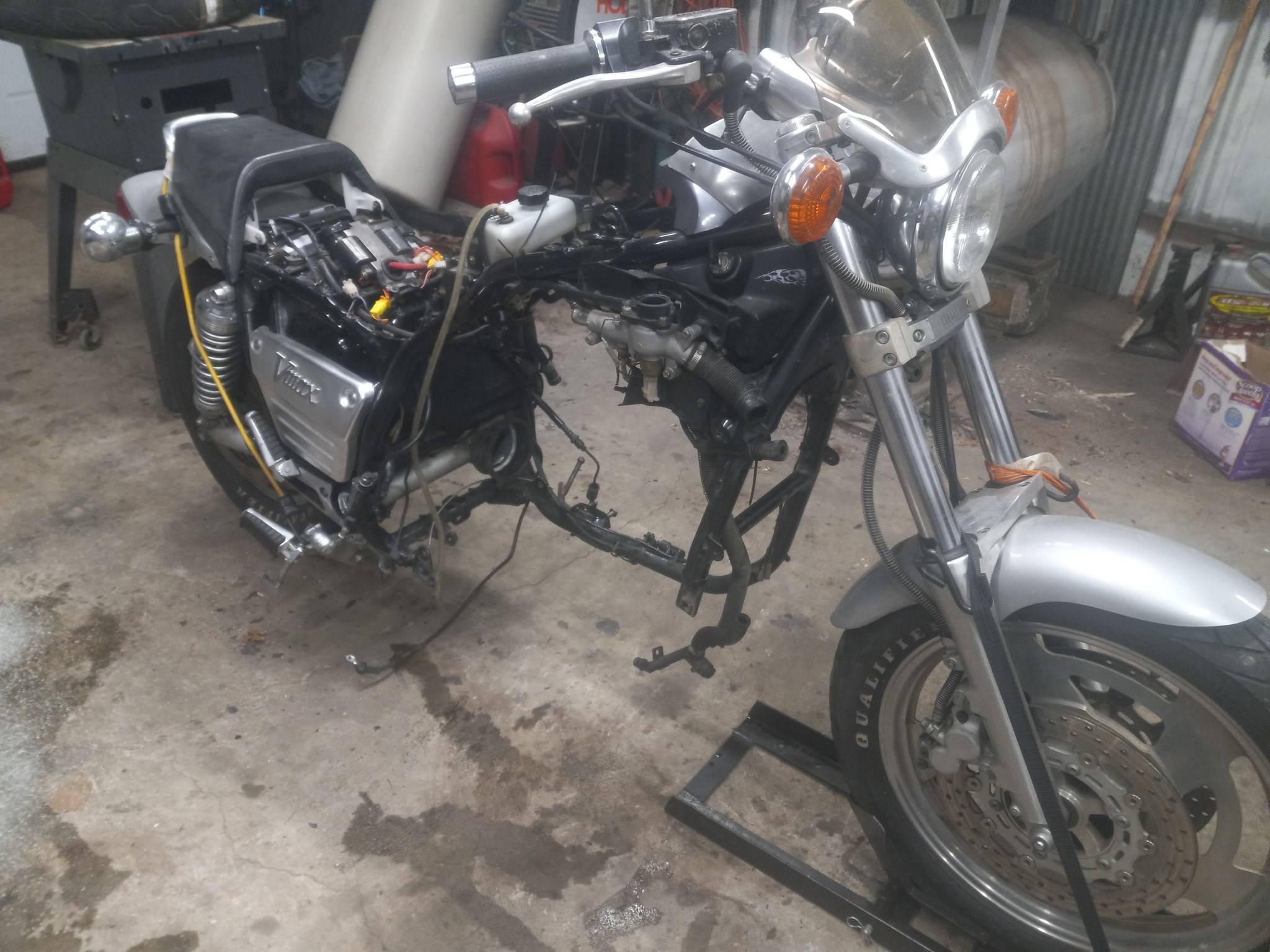
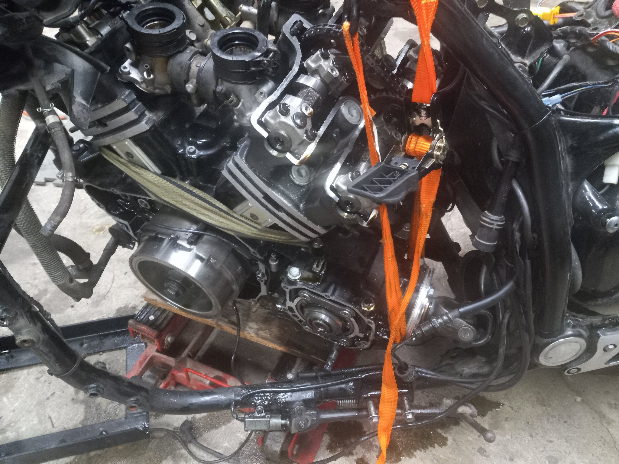
Haven't bothered to do a video but here's the steps we put together some years ago.
Removal of the Vmax engine in 20 simple steps!
*Note - many of the steps listed can be done in alternate order.
**I also may have missed some minor stuff and will update this as needed.
***Eventually I will put pictures with each of the steps
1.) Put Bike on Centerstand, ATV Lift, or Alternate Method
*If centerstand is available, this is easy!
**If no centerstand then see notes in swingarm removal for additional tips that you can use later.
2.) Unhook the Neg Cable from the Block
*Located Right Rear of engine
3.) Remove Cosmetics
a.) Scoops
*Don’t forget about the plastic heat shield on the coolant junction as this is easy to lose
b.) Side Covers
*right side optional
c.) Faux Tank
d.) Front Seat Section
e.) Remove lower intake covers
*#3 Phillips and DO NOT use the Hand Impact Driver as this will break the intakes
4.) Remove Exhaust
a.) It’s all got to come off and sometimes it isn’t fun
b.) If you still have the stock exhaust you’re probably going to break the small screws holding the rear heat shielding on
*The stock mufflers are HEAVY and be careful If you don’t want to ding them up.
**Don’t forget about the bolt underneath near the centerstand if you still have the stock mufflers
5.) Drain Oil
a.) Though this can be done anytime you’ll have more room with the exhaust out of the way.
***There are additional places that oil will drain from then just the pan so save it aside for now.
6.) Drain Coolant
a.) The drain plug on the bottom of the waterpump is a good place to start.
b.) An additional place to drain fluid from is under the cylinder cover plates.
*These are located just under the head on each cylinder
**Use a manual impact to get the countersunk allen loose
***Use a spark plug to remove (and install) the plugs that are located under the plate
****Coolants going to run all over the place so I hope you have a good drain pan
*****A large baking pan actually works well!
******Reinstall the plugs anytime to keep things clean while you’re removing the engine.
c.) Remove the drain cock from the t-stat housing. One bolt holds it on.
*You can remove the cock completely if desired. Just held on now by the two small hoses
d.) Unhook the large hose from the radiator to the tstat housing
*You can remove the radiator if desired but not required
e.) Unhook the small hose from the coolant junction tube (leads to the area near the left front carb)
7.) Disconnect the clutch line connection
a.) This is at the left rear of the engine. It’s going to drain fluid so where’s your pan?
b.) Tie the hose up to the frame out of the way (after it’s drained)
*You can zip tie a baggie on the end with a paper towel inside to catch any residual that will inevitably drain.
**Alternatively, You can remove the mid gear cover and remove the entire slave cylinder as an assembly.
***If removing the slave you need to be straight on with the allen wrench as those bolts get corroded in the block
8.) Remove the Pegs/Mounts/Shifter/Brake
a.) The Left Side peg is easy
b.) To remove the shifter you need to take the two bolts holding the main bracket (passes through the mid gear cover)
remove the pinch bolt in the splined shaft clevis.
*Note the small “dot” on the end of the shift shaft and it’s relation to the pinch area of the clevis.
c.) Remove the right side peg. The brake pedal can stay attached.
*You will need to unhook the spring from the brake light switch
**OR remove the bolt through the bracket and let the whole mess swing aside
***If you opt to remove the pedal and peg completely just note the spline alignment mark and pinch area relationship
d.) Remove the 2 bolts holding the rear brake master. Pull the whole mess rearward and tie in place out of the way.
9.) Remove the mid gear cover
a.) Remember the drain pan, you’re going to need it! The bottom most bolt should have a copper washer on it to seal the block.
*There is another drain bolt back under this cover if you want to get more oil out of the block.
10.) Unhook the electrical under the left side cover
a.) Stator Wiring Connectors (3 wire connector)
b.) Pickup Coil Connector (2 wire orange/black for 90-07, or a 6 wire connector (*5 wires used) for 85-89))
*This connection point will be up nearer the back of the battery
c.) Oil level and Neutral Sensor wires (Bullet Connectors)
*These are the only connectors you can mix up back here so label em or swap around if you hook em up wrong later
d.) Remove starter wire from solenoid located on top of battery (big thick wire - Black in color NOT red).
*Remove bolts holding rear coil bracket if needed.
e.) Side Stand Switch (2 wire connector)
*All wiring except the side stand switch needs to be coiled up and zip tied to the engine
**The guide for the clutch line works well for this.
11.) Coil up the side stand switch wiring out of the way to the frame, then Reinstall the Mid gear Cover with a couple of bolts or all 4.
*Don’t forget that the bottom bolt is the one with the copper washer.
12.) Remove the rear brake caliper
a.) Just remove the two bolts, and unhook the hose so it can “hang” in place. Zip tie up if desired.
13.) Remove the rear wheel/swingarm/shocks
a.) Shocks are optional for removal from the frame
b.) The entire mess can be removed at one time or one part at a time.
*it’s all going to go back together one part at a time (though I can do it as one assembly - most can’t).
c.) Remove the two pivot bolts (one under each chrome cover).
*The right side has a jamb nut to loosen first
*The left side has a locking tab that needs bent up first
d.) If removing as a complete assembly just roll it on out.
*The front is going to fall down so be careful.
**If left together leave the front of the differential pointing up since it will drain fluid otherwise
***You also can’t leave the rear diff laying flat - it will also leak out of the front.
14.) If you don’t have a centerstand this is a great opportunity to prop the bike up.
a.) Using 2 long bolts through the original muffler mounting holes you can set this on jack stands or an ATV type lift
15.) Remove the Middle Drive Gear
a.) Remove the rubber surround first. Just pull it off.
b.) The drive gear assembly is the part with the ujoint sticking off the back of the engine. 3 Bolts and a tug (You are good at tugging!)
*There are some shims that will also fall out - don’t lose them.
**You can loosen the 2 bolts on either side of the assembly from the top down if needed.
***Be careful if you pry on the flange since it’s not super strong.
16.) Remove the carbs/airbox
a.) Remove the screws holding the overflow tubes to the top of the airbox
*Put the screws back in the airbox so you don’t lose them
b.) Give the airbox a yank and it should come right out.
*You should loosen the clamps at least by the time you have it out so the boots don’t deform too badly while you fix the engine.
c.) Of course you need to unhook the fuel line - draining the carbs is optional
d.) Getting the carbs out of the intakes can be a challenge (especially if it’s cold out).
*Use a hair dryer to warm up the boots. This will great aid getting them out.
e.) Unhook the throttle cables from the junction box under the left neck cover.
f.) Slide the carbs out the left side
*don’t turn them on the side or upside down unless you want fuel to pour out!
g.) Unhook Vboost Cable. One long special shaped Phillips screw.
**intake can stay on if desired if only doing something like trans repair.
h.) Unhook vacuum hose from left front intake
17.) Support the engine for removal
a.) A simple floor jack works well. You can either put a small section of plywood down or jack right on the oil pan.
*Optimal placement is where the jack catches the pan front fins and the pan rear fins.
**Just enough pressure at this point to have the jack touching but not lifting the engine.
18.) Remove the frame cross support from up front
a.) This is where the horn is mounted. Just unplug the horn - no need to unbolt it from the bracket.
*You may need to loosen the main bolts holding the right lower frame section in place
**If you have engine guards they need to come off at this time too.
***Three bolts per side.
19.) Remove the frame/engine access section, and left side support
a.) You’re almost there.
*2 Bolts up high, 1 Nut on the upper mount, 2 Allen bolts at the rear (behind the peg area), and 1 Big Bolt in the rear.
b.) Remove the “triangle” front the left side. 1 Nut on the mount and 2 bolts in the frame.
c.) Remove the large bolt in the left rear engine mount
20.) Remove the engine!
a.) Jack the engine up with attention to the valve covers as well as rear engine mounts.
*The engine mounts on the rear need just enough clearance to slide out.
**If the valve covers want to hit first then you need to reset the jack a little rearward.
b.) With the engine up just enough to clear it should slide straight out to the right.
*You can sometimes tilt the engine at the top if needed or even slightly turn the engine at the front out of the frame.
21.) Reinstall the swingarm for chassis mobility
a.) If you want to have the chassis able to roll around simply put the swingarm assembly back in place.
*For you smart guys that read the beginning and see I said 20 steps. This 21st step is not part of the engine removal lol!


 Here's pics of an ATV jack I once used to hold it
 8 by Tim Brown, on Flickr[/URL]
 4 by Tim Brown, on Flickr[/URL]